![]()
![]()
|
|
|
|
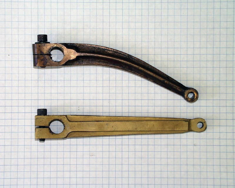
UP 844 Catches The Flu(e)Part III - Installing The New BoilerBy Chuck Hackett, November, 2001 (you can click on the photos to see a larger versions) (Click here to be notified when this page changes) While the boiler was off the locomotive, my first task was to replace the brake actuator arm that runs from the brake cylinder down to the shaft that actuates the brake beams. This arm had become severely bent in a mishap. How did this arm get bent? Well, I guess we have time for a short story ... We were at St. Croix RR in Hudson, Wisconsin (a great facility) and a friend of mine was running my Northern training his mother at the throttle during a night run when, coming out of a tunnel, they encountered a flashlight that had been dropped on the track. The flashlight somehow made its way under the pilot and wedged itself between the track and the rear driver brake beam. The brakes were applied at the time so the cylinder was extended but the flashlight forced the brakes off and the cylinder didn't move so the arm lost!
The grid here is .25". The lower arm is a new one - that's what it's supposed to look like! :-) It took me a couple of days to accomplish this because I had to remove the
front driver, including the siderods, to gain access to the shaft that the arm
is attached to.
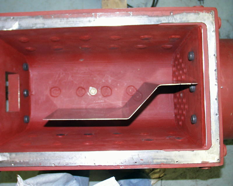
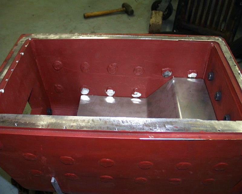
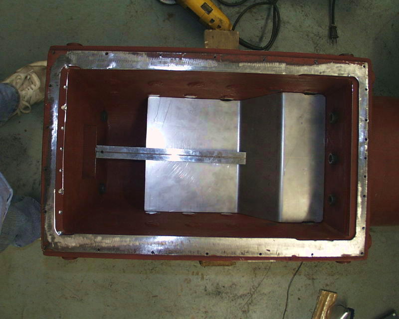
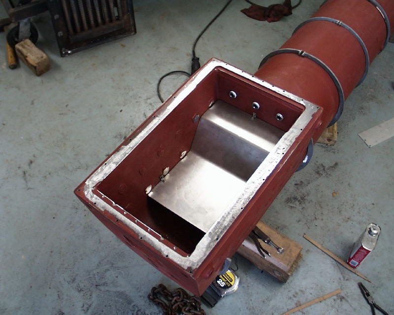
Installing The Firebox ArchOne of the first tasks was to fabricate a new arch. An arch has a dramatic effect on the efficiency of the boiler because it forces all the gasses to travel to the rear of the firebox and then forward towards the flues at the front of the firebox. If there were no arch present the gasses from the forward end of the burner would be allowed to "short circuit" directly to the lower flues. One item up for discussion is the optimal length of an arch in a propane fired locomotive boiler. A long arch (as I have currently) forces a long gas path (good) but shields most of the crown sheet and part of the firebox sides from the radiant heat of the fire (bad). I tried to shape the arch described below to maximize the amount of firebox sides exposed to the fire.
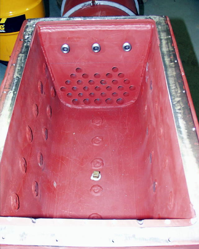
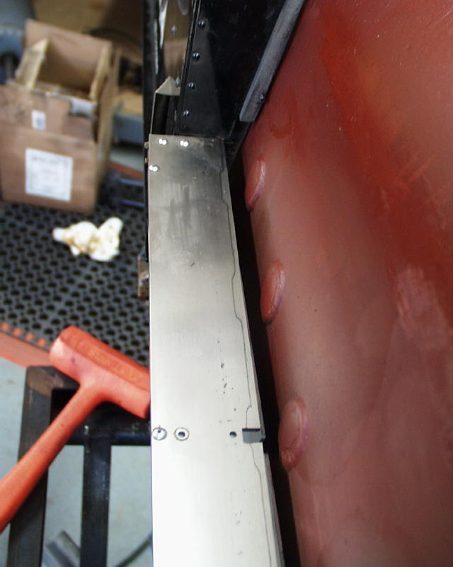
This photo shows the the firebox before fitting the arch. I have already
ground the bottom of the mud ring to make it flat to accept the burner.
Note that I have also plugged the hole in the center of the crown sheet to
prevent debris from entering the boiler. Later a fuseable plug will be
installed in this hole. The arch was constructed from a piece of 16 gauge stainless steel. It is held in place by three stainless steel angle brackets fastened to the boiler with stainless steel hex cap screws. (the third photo has a 12" ruler for size comparison)
Miscellaneous Steps
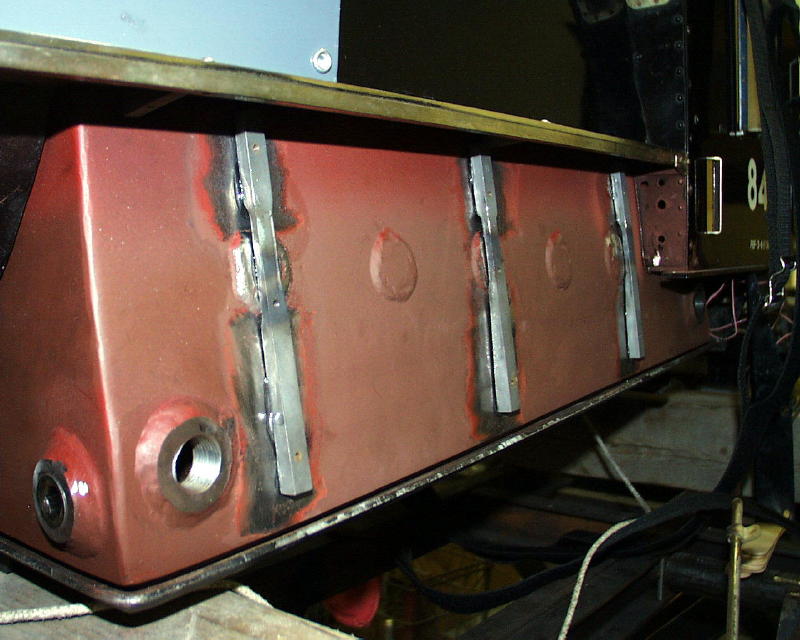
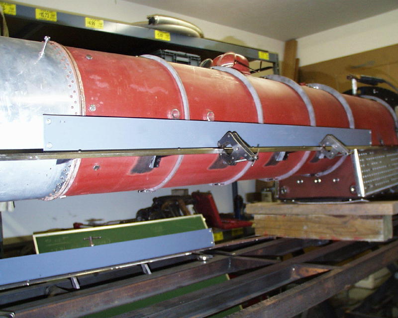
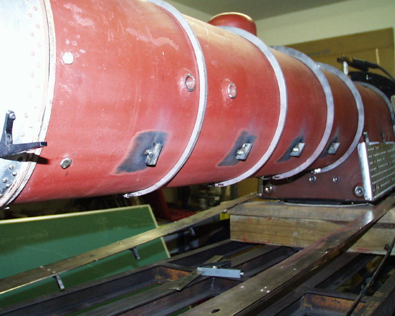
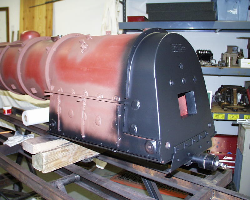
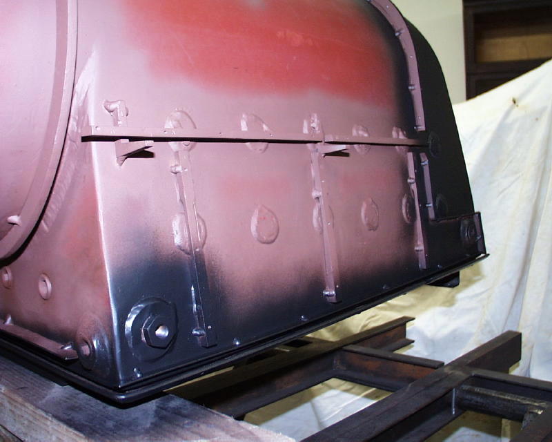
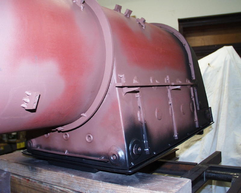
Attaching Mounting Points To The BoilerFor a long time I was in a quandary about how I was going to get the attachment points (handrail stanchion supports, footboard supports, steam dome foundation, false firebox side supports, etc.) placed in the correct position on the new boiler under the outer sheet metal (boiler jacket and false firebox sides). I was reusing the old sheet metal as the template to be sure that the bolt holes in the attachment points would match up with the holes in the sheet metal so that I didn't have to make new jacketing, etc. The question was: how do you fasten the attachment points to the boiler under a sheet of steel? Obviously there was no way to get my MIG welding tip in there. After some thought, I decided that I could bolt the points to the appropriate sheet metal section, apply epoxy cement to the attachment points and install the section. After the epoxy cured I unbolted the attachment points from the sheet metal, removed the sheet and the points remained in place and ready to be welded to the boiler! One problem with this method was that if there was any epoxy where I wanted the weld, the epoxy had to be removed prior to welding. This was because the heat of the welding would vaporize the epoxy and contaminate the weld. First came the false firebox sides ...
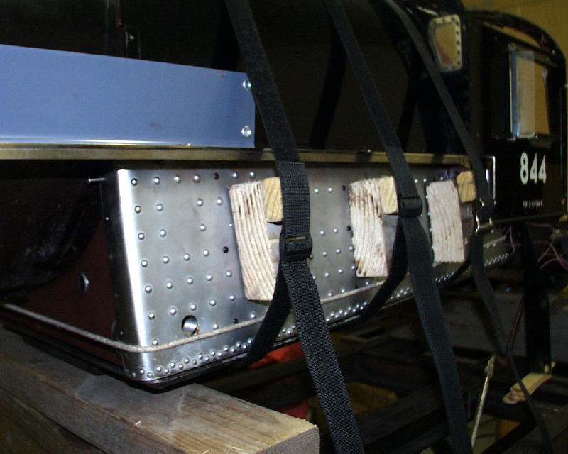
Next a more difficult challenge - the footboard supports. More difficult because the footboard sagged without its supports. This was solved by using a piece of steel that had a 90 degree bend in it forming a sturdy "straight edge". This was clamped to the foot board to prevent sagging and the footboard was installed on the forward and rear supports which had been located previously.
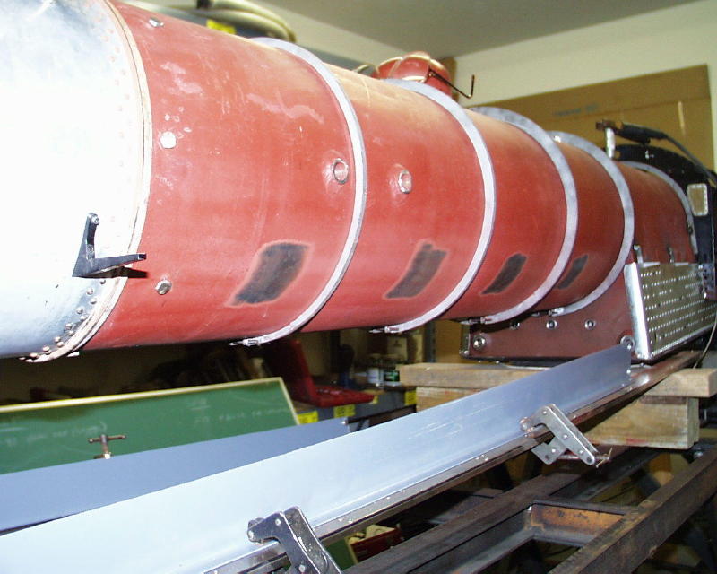
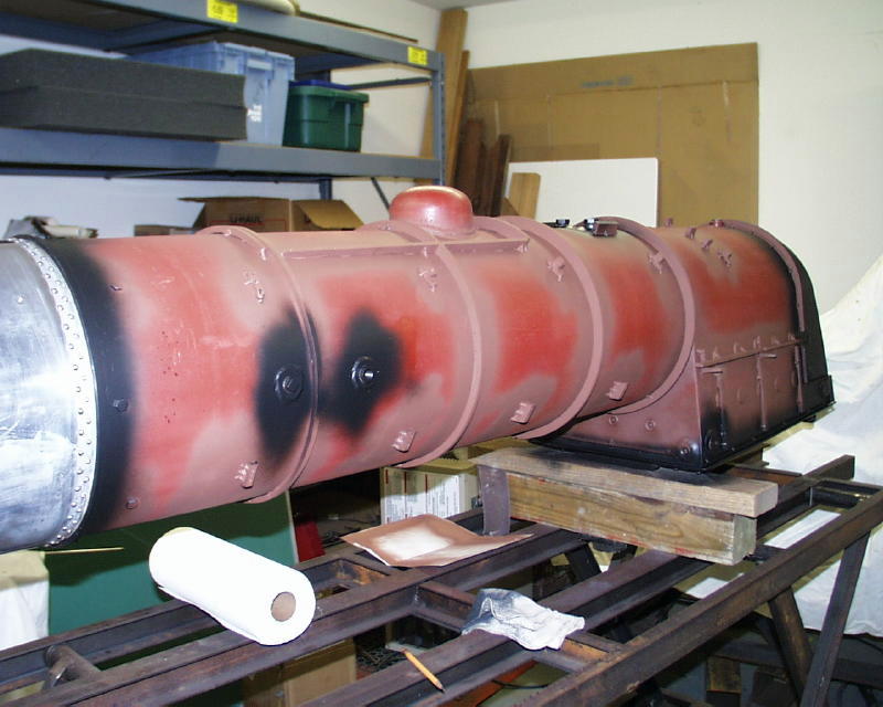
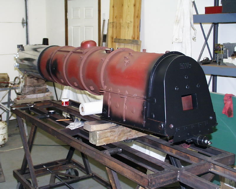
Current Status (11/26/01)I have finished fitting all of the sheet metal elements to the boiler along with all attachment points for the handrails, etc. All welds and bare metal have been painted with rust inhibiting primer and and the smokebox has been attached and cleaned.
All this work was actually much more involved than I have presented here. I had the jacket, cab and footboards installed and removed about a dozen times! Fit, measure, file, grind, fit, measure, file, grind .... Ray constructed the boiler as close as possible to the old one but, invariably, when you are bending and welding 1/2 inch steel plate things don't come out exact. There were areas where adjustments had to be made to some of the old components. The firebox was about .25" wider than the old one. This necessitated modifying the cab, footboards, etc. to accommodate the new width. More progress notes to come soon ...
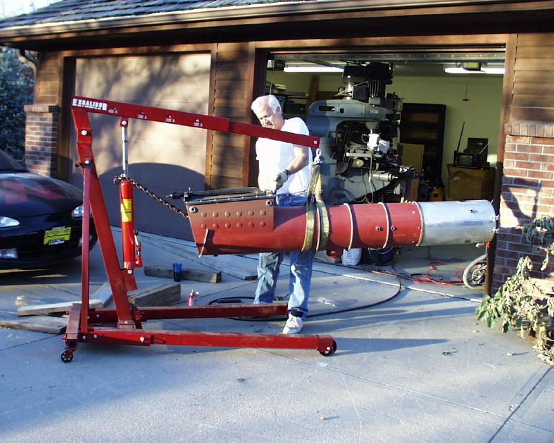
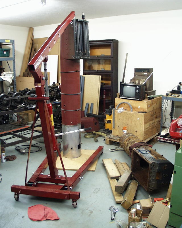
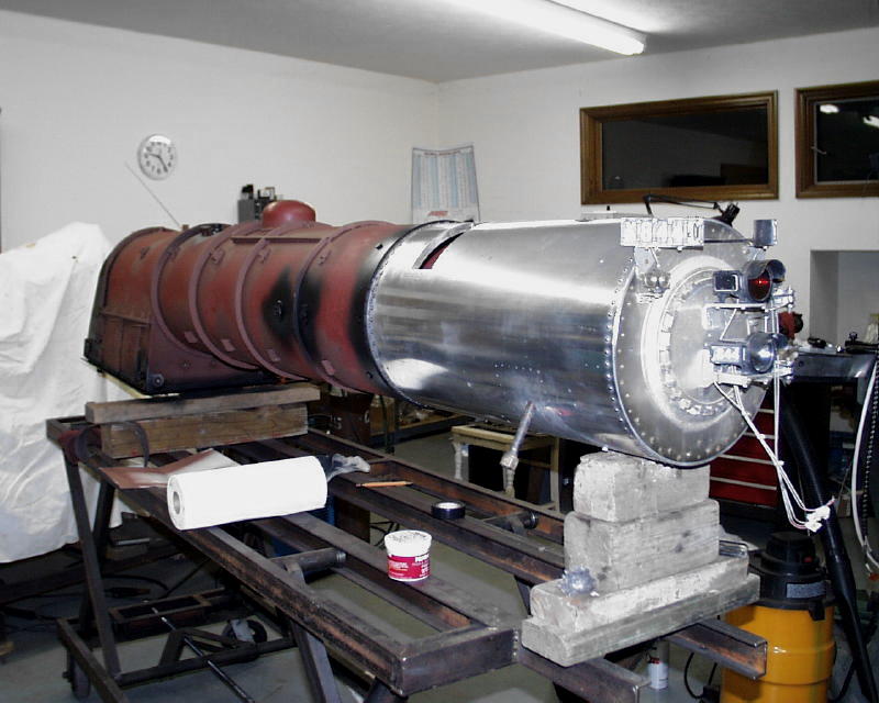
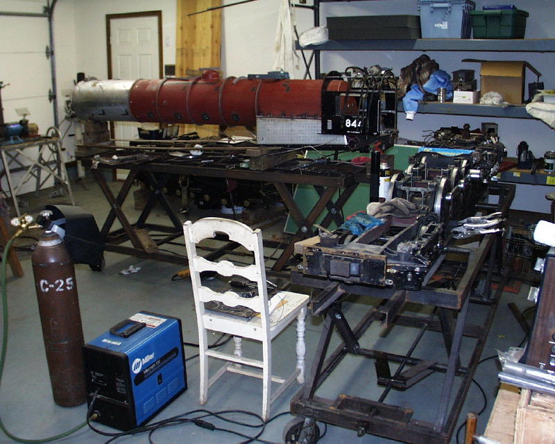
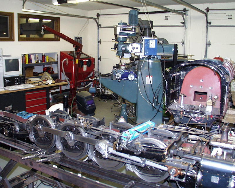
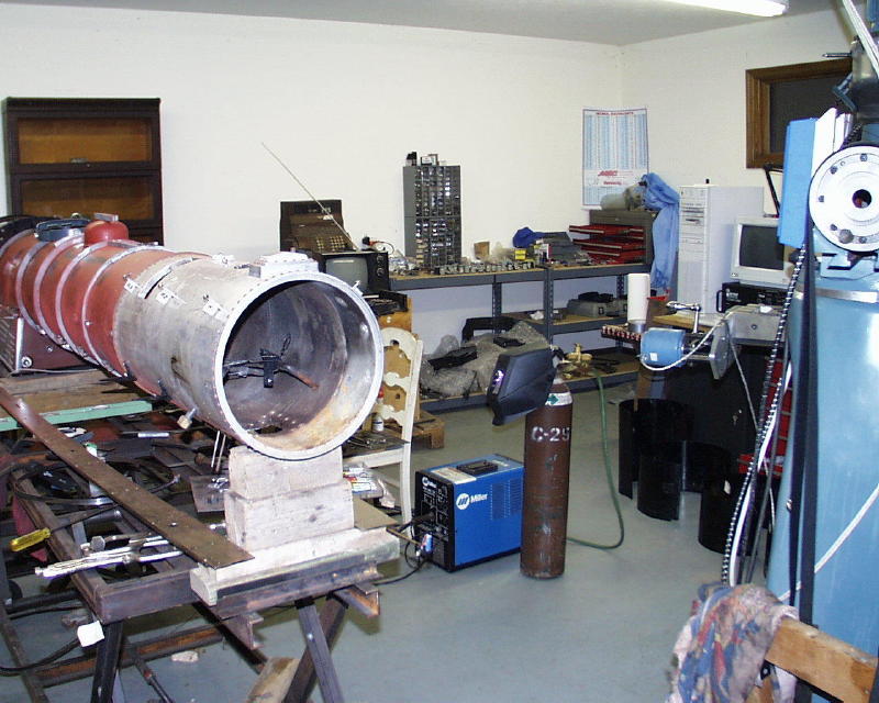
The Work AreaI'm embarrassed to show you these scenes. Before I could start on fitting the new boiler I had to move my shop from the basement to our two-car detached garage. Before I could do that, I had to build a 16 x 24 foot building to hold all the "stuff" that was in the detached garage! So I had projects stacked up end-to-end. Since I needed to have the locomotive finished by January in preparation for a trip to Florida I decided that I didn't have time to completely setup the shop before starting on the locomotive. So we moved the large equipment to the new shop and I started fitting the new boiler with tools, etc. on tables instead of properly hung. So, things are just kind of packed in for the moment. After the locomotive is finished I'll concentrate on laying things out properly. You'll notice a Miller 130 MIG welder (with C-25 shielding gas - Argon/CO2 mix) in the photos. Before I got this unit I couldn't weld to save my soul. Now I can do a fairly decent job of it. You can also see the two double scissors stands I built for the locomotive and tender.
For installation progress see Part IV - Installing Jacket and Lagging Click here to return to Part I I can be contacted via eMail. Please let me know if this page doesn't seem to be formatted correctly for your browser or if you have suggestions on how I can make it better.
|