
![]()
![]()
![]()
![]()
![]()
![]()
![]()
![]()
|
|
|
|
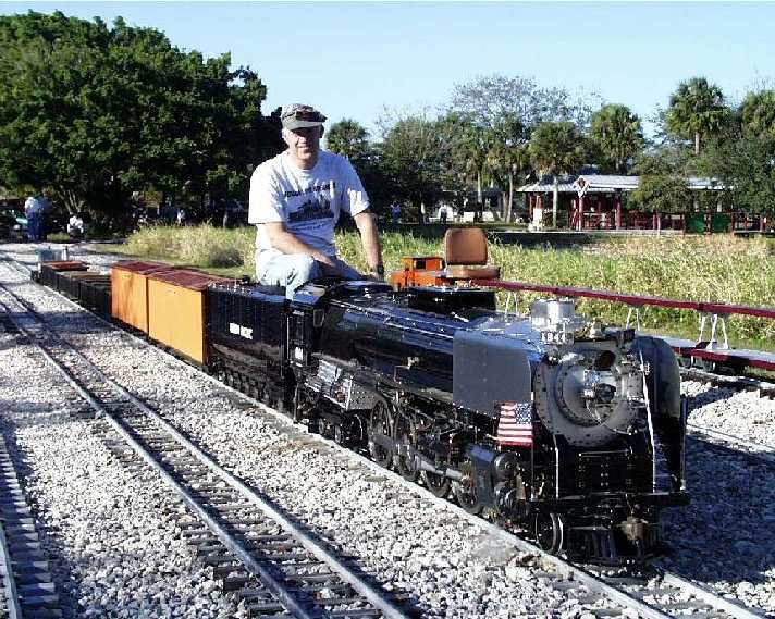
UP 844 Catches The Flu(e)By Chuck Hackett, October, 2000 (you can click on the photos to see a larger versions) (Click here to be notified when this page changes) Every year in February I go to the Florida Live Steamers meets. February of 2000 was no different.
I had just spent the previous four months completely tearing down the engine and tender to give her a new coat of paint and some backshop work to get her ready for IBLS 2000 and she was looking great. The first run was the Southern Division of the Florida Live Steamers at Tradewinds Park, North of Ft. Lauderdale. I should have taken it as a bad omen when we filled the tender for the first
time and a stream of water was noted coming from the back of the tender!
It turned out to be just a mounting hole for the class lights which hadn't been
remounted yet. This problem was easily fixed by just putting a bolt in the
threaded hole.
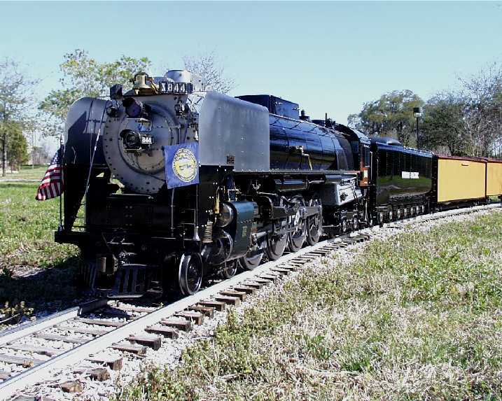
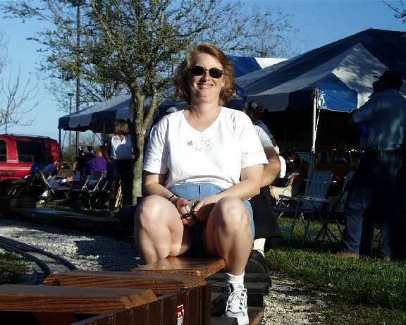
Things were going well later in the week when we we arrived at the Central Division of the Florida Live Steamers in Largo (near Clearwater). Even Wife Joan was enjoying the view from a passenger car behind my locomotive (well, I guess it's half hers). That's when the storm clouds started gathering. I had lit the fire (propane) for a day of running. The pressure was up to about 60 psi so I lowered the fire, switched the blower from air to steam, checked the wheel chocks and noted that the pressure was rising slowly. I then went to grab a cup of coffee to bring back and drink while she finished coming up to operating pressure. While walking back about 2 minutes later I thought "that's strange, there's lots of smoke coming from my stack". I assumed it was from another locomotive parked visually behind mine because propane fires don't usually smoke. As I got closer I realized that it wasn't smoke coming from my stack, it was steam - and lots of it! When I got there it was obvious that there was a major problem. Besides the steam coming from the stack the pressure was dropping rapidly and worst of all, water was pouring out of the bottom front of the firebox. I killed the fire and we moved her to a steaming bay to check things out. It didn't take a rocket scientist to conclude that a flue had developed a rather large hole. After the initial bout of depression wore off we started formulating a plan.
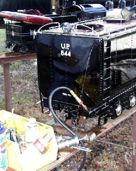
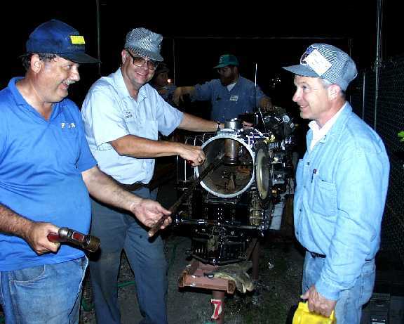
We decided to machine two tapered brass plugs (the use of a shop was generously donated by Don Mann, one of the Largo members) and hold them in with a piece of .375" "all thread" running the length of the flue. Obviously, this plan took much longer to devise and execute than it takes to tell about it (note that it's dark in the above photo). From the time the tube ruptured until I was again running was about 11 hours. As we reflected on the events the obvious question was: Was this one weak tube or is this the beginning of the end for this boiler?" I would have to wait until the IBLS meet in August for the answer ...
August 2000 IBLS TourWe started on our 5 week IBLS tour trip at the British Columbia Society of Model Engineers in Burnaby, BC. Everything was going fine until we noticed that 844 was starting to steam harder and it seemed like we were getting a lot of steam out the stack - even when stopped with the blower off :-( So, off to the steaming bay we went to have a look in the firebox door. Sure enough, there was a stream of water (much smaller than in February) coming from one of the upper flue tubes.
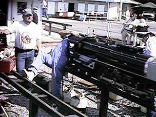
(Will Jordan photo) With the help of a lathe and other tools in the well equipped BCSME shop, BCSME members and other Live Steamers we made plugs and sealed off two more leaking flue tubes. We got 844 back on the rails to finish the IBLS meet at Burnaby and ran the rest of the IBLS tour (including lots of running on the grades at Train Mountain) and the rest of the year. The three plugged flues resulted in a minor reduction in steaming capacity. As a side note, all the flue plugs were made from brass. In Burnaby we tried using wood but this failed because all we had was soft wood. I understand that hardwood (Oak?) would have worked better. Part of the problem may also have been that, since we didn't trust them to hold by just driving them in, we had a hole in the center of the plug to accept the threaded rod to hold them in. I now knew that the one flue that failed in February did, apparently, indicate a bigger problem. I decided drastic action might be called for. After our last club run this fall I decided to remove the boiler and take it to Ray Pennell at Steam Age USA, Inc. (Cypress Hill, Texas, near Houston, 281-516-2713) to see if only the flues needed attention or if more drastic measures were required.
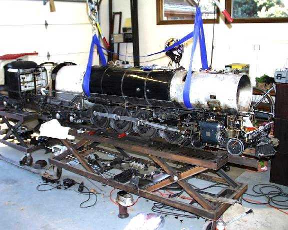
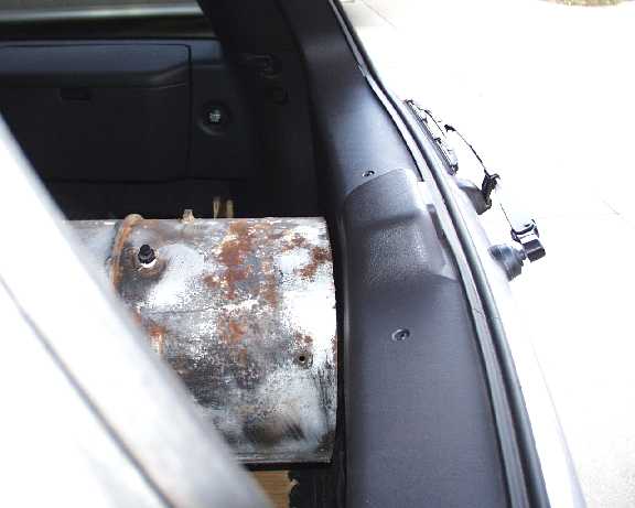
Removing the Boiler
The first task was to remove the boiler from the engine (no small undertaking)
and remove the cab and smokebox. To my knowledge this is the first time
the smokebox has been off the boiler since the locomotive was finished in
1969.
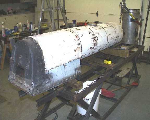
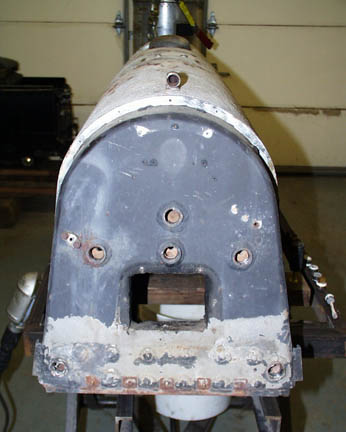
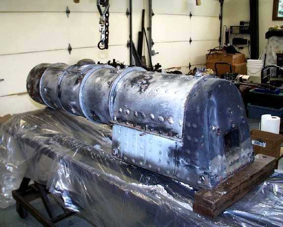
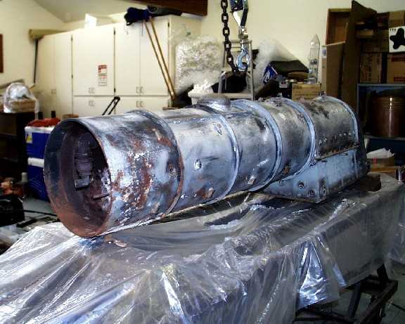
Next I removed the lagging cover and insulation. In this case the insulation is an asbestos based compound (no longer available, I believe) that is semi-hard but reduces to a thick paste and can be toweled after water has been added. Here's what the boiler looked like after the asbestos insulation was removed:
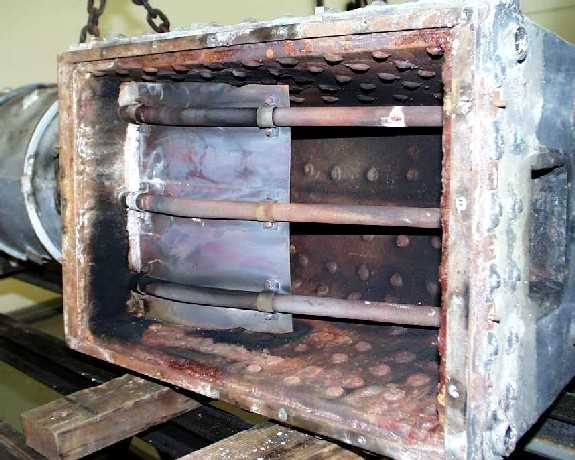
The barrel of the boiler is 12" outside diameter and 11.5" inside (.25" rolled sheet) containing twenty two .75" welded steel flue tubes and four .5" tubes. The firebox inside dimensions are approximately 12" x 18" and contains three arch tubes (some call them siphon tubes) to promote circulation.
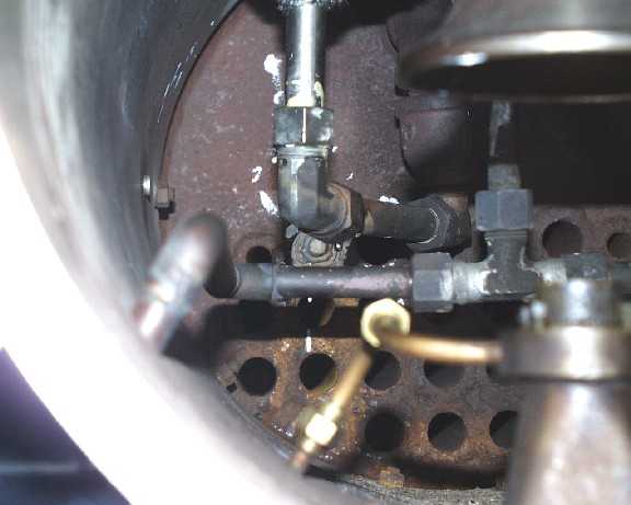
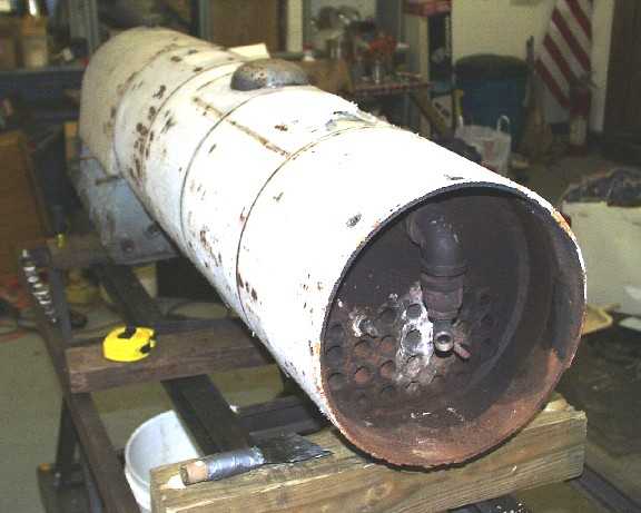
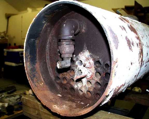
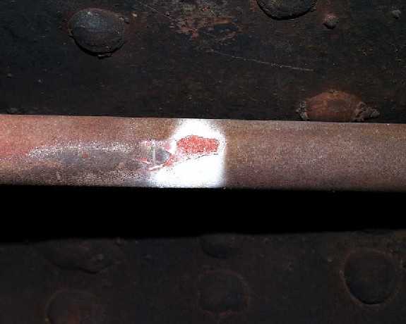
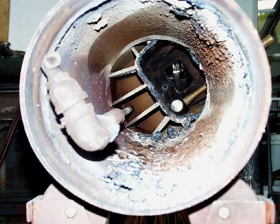
While examining the firebox area I noticed that one of the tubes (upper one in the above photo) appeared to have an abrasion mark or area of erosion surrounded by a white deposit on the lower side (facing the propane burner). I'm at a loss as to what caused this. On the inside the tubes are coated by about a .050" thick layer of fine powdery substance. Other than that, they appear to be in good shape. Here is a photo of the spot I'm referring to:
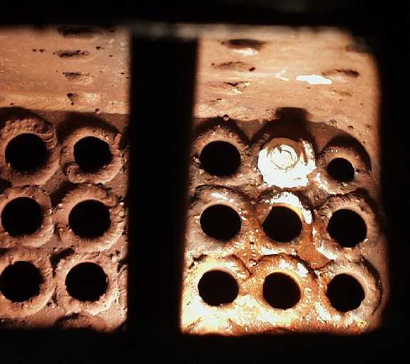
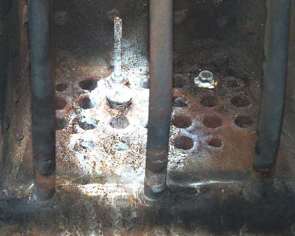
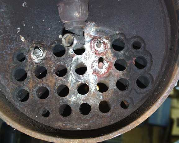
Here are photos of the firebox and smokebox ends of the flue tubes. Notice that the plugs put in at Burnaby were leaking a little. You can see all three plugged tubes. In the photo from the firebox end the (now plugged) flue that went in February is the single one on the right, the two flues that went in August at IBLS are on the left:
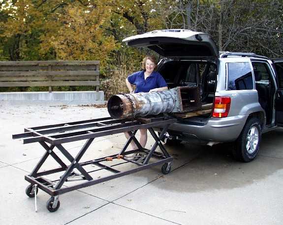
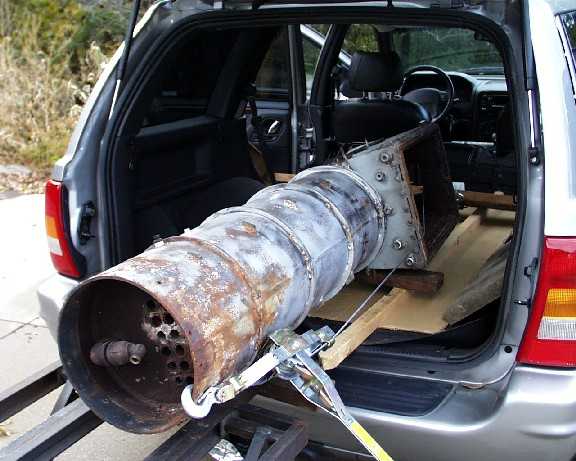
Trip to TexasThe next task was to load the boiler into my Jeep Grand Cherokee for the trip to Steam Age USA in Texas. A fork lift would have come in handy but Joan and I managed to get it in using my double scissor engine stand. I used a large come-along attached to an overhead beam in the garage to place the boiler so that the firebox was overhanging the end of the engine stand. We then wheeled it to the car and lowered the firebox onto some boards placed in the car.
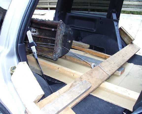
Then I used a "come along" to draw the boiler into the car:
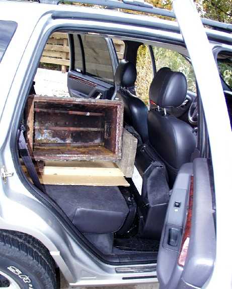
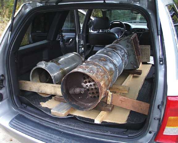
I was able to push it in the last bit and placed a board against the seat to distribute the force in the event of an emergency stop. After putting in the smokebox and blocking the boiler to prevent shifting we were ready to go. Note in the second photo that there was no room to spare!
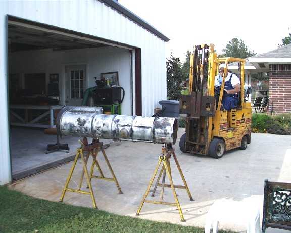
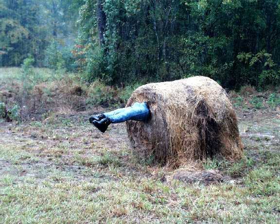
My friend and steam traveling companion Larry Blecha kindly offered to make the trip with me to help with the driving. On the trip down we saw an example of warped Texas Humor! The InvestigationAfter a short (?) 20+ hour drive from Omaha to Houston we arrived at Steam Age USA. Luckily Ray has a fork lift (I guess he's tired of stressing his back!).
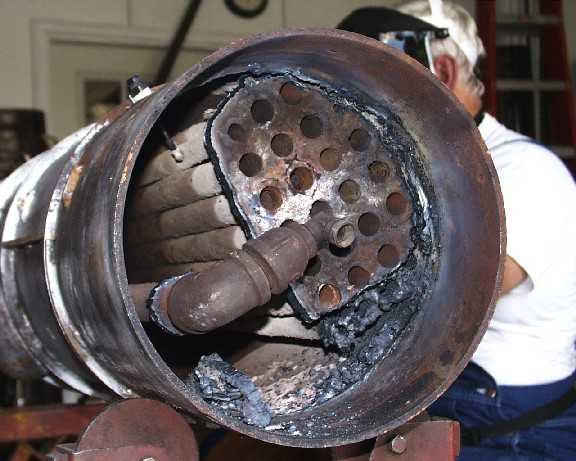
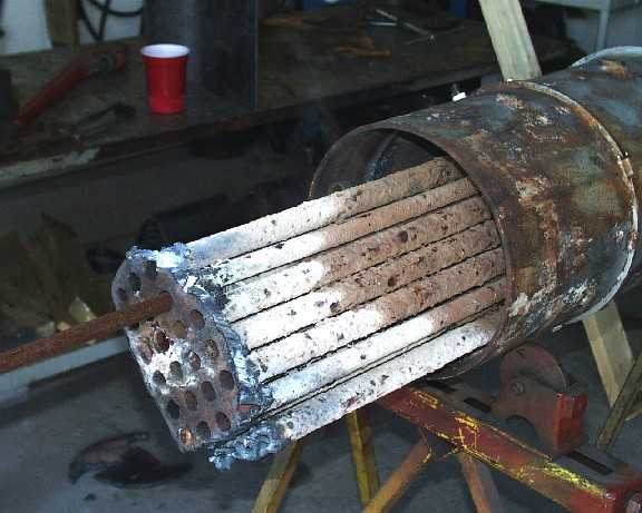
Now we had to see what shape the boiler was in on the inside. Ray used a cutting torch to remove most of the front flue sheet and free the front of the tube nest from the shell. In this photo we can begin to see that the tubes were in bad shape.
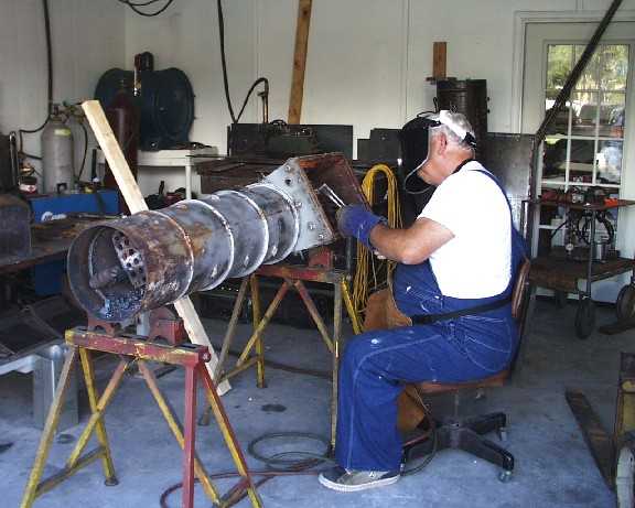
Next Ray cut out the rear of the tube nest from the firebox.
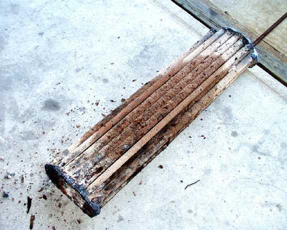
After removing the tube nest we wondered how it generated steam or held together at all! The tube nest is almost solid with scale and corrosion. The darker color near the middle of the tubes is due to the fact that they were damp even though the last run had been at least two weeks earlier and the firebox was dry (the ends of the flue tunes are dry due to the heat from the cutting torch). I suspect that once deposits started forming on the tubes the deposits retained moisture and accelerated the tube corrosion.
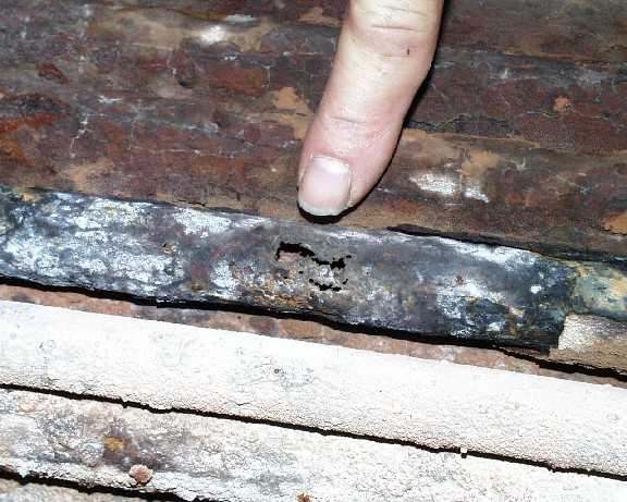
Here is a close-up of the hole in the tube that failed in February at the Florida Live Steamers meet.
Even though the tubes were in bad shape, the barrel, stays, firebox and waterlegs were in fairly good condition. In the following photo the debris in the bottom of the barrel came off the tube nest as we removed it. The barrel looks pretty good except for the bottom of the barrel (upper right) shows some deposits. After scraping this away there was considerable corrosion. The corrosion here was of concern since the barrel was formed from .25" thick steel with a seam weld at the bottom (in the middle of the corrosion). Ray noted that when he welds barrels he places the seam about a third of the way up on one side to get it out of the corrosion-prone area.
The DecisionNow that I could see the overall condition of the boiler we discussed options with Ray of Steam Age. I had always planned on replacing the flue sheets and installing rolled copper flues but now I had to decide if I needed/wanted to go further. I was concerned about getting another 20 years out of the existing barrel. Ray was concerned about being able to replace the rear flue sheet properly, especially getting a proper full penetration weld between the flue sheet and the crown sheet. In order to get a proper weld he felt it best to replace the firebox. In the end, I decided to have Ray build a new boiler due to:
My welding skills are not up to a boiler like this and I'm too busy at the moment to acquire and practice the skills required so I've hired Ray to build a completely new boiler for me. Some of the high points of the new boiler will be:
It's interesting to note that the prototype Union Pacific 844 is currently undergoing firebox replacement in Cheyenne, Wyoming herself and probably won't be steaming again until 2002. I'm sure it's costing Union Pacific a lot more than my new boiler is costing me. So, in a sense, my troubles are small ones! :-)
Stay Tuned ...I will post photos and notes on the new boiler here when I receive it. I will also be adding various sensors (pressure, temperature, water & gas flow, etc.) to the boiler. This will enable me to do some controlled experiments on steaming efficiencies under different conditions (with and without siphons, with and without superheaters, etc.). For an update on the arrival of the new boiler see Part II - New Boiler Arrives Home
Steam in Houston Side Trip
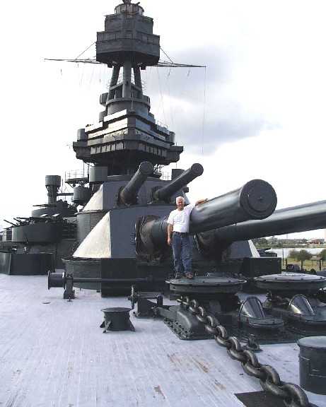
Before we left the Houston area Larry and I took a side trip to see the Battleship Texas. This ship was commissioned on the 12th of March, 1914 and served in WWI and WWII. Highlights of her career were the shelling of Omaha Beach at Normandy and supporting the invasion of Iwo Jima. The main batteries consisted of ten 14 inch/45 caliber guns in 5 turrets. She could throw a 1,500 pound shell to a range of 13 miles. She was originally supplied with coal fired boilers but they were replaced with oil fired water tube boilers prior to WWII. Propulsion was provided by two large triple-expansion engines. Each engine has one high pressure cylinder, one medium pressure cylinder and two low pressure cylinders. When we boarded the Texas we couldn't find a map showing the way to the engine room. I passed a compartment where I heard voices so I knocked and said that we were steam enthusiasts looking for the engine room. A gentleman said that he would show us the way. He turned out to be John Ferguson who is the Restoration Planner and Ship's Historian.
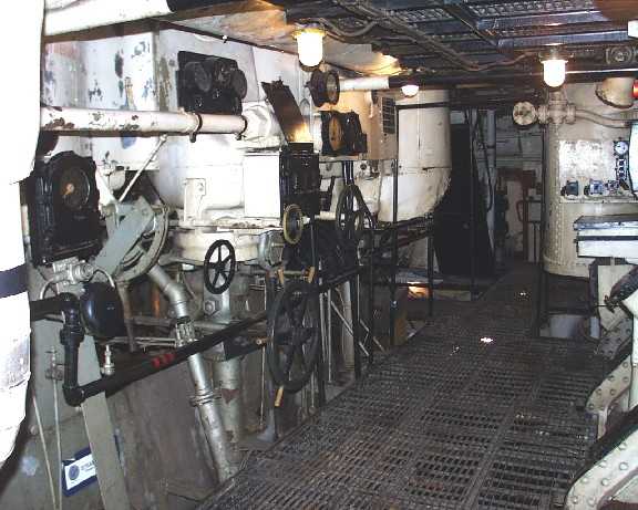
John guided us to the engine room which we were allowed to inspect to our hearts content. I was surprised to see several Westinghouse "Locomotive" simplex steam air compressors on the bulkhead in the engine room. We discovered that some of the engine control systems were pneumatic as well as several other air systems. After we had examined the engine room (including the
"shaft ally") John asked us if we'd like to see one of the boiler
rooms. We, of course, said Sure! He disappeared for a few minutes an
reappeared with a head mounded light for him and flashlights for us because the
boiler rooms are not currently equipped with working lights.
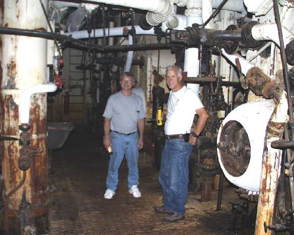
After going through two bulkhead hatches and one (very heavy) deck hatch and down a very narrow set of stairs we arrived at the pitch black boiler room. The Texas has three boiler rooms each with two boilers. It didn't take much imagination to sense that during operation this would have been a very hot and noisy place! The boiler room photo was taken in almost total darkness. That's Larry on the left and me on the right. The large round object to my left is the lower left mud drum of the Port side boiler. It took a minute for our eyes to readjust after the flash went off. We noticed a small closet with a door. It contained some electrical stuff on the walls. I asked John "What's that, a phone booth?". He said that's exactly what it was. Turns out that it was so noisy in the boiler room they needed a partially sound proofed room to talk to the bridge and other parts of the ship.
I can be contacted via eMail. Please let me know if this page doesn't seem to be formatted correctly for your browser or if you have suggestions on how I can make it better. This page has been viewed
|